PSoc62™开发板之ADC读取电压
实验目的
2.使用OLED显示电压值
实验准备
- PSoc62™开发板
- 电位器
- SSD1306 OLED模块
- 公母头杜邦线
组件配置
ADC配置
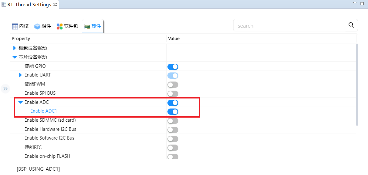
RT-Thread的HAL层目前只适配了ADC1,在RT-Thread Settings里边只能看到一个选项,我们把它开启了
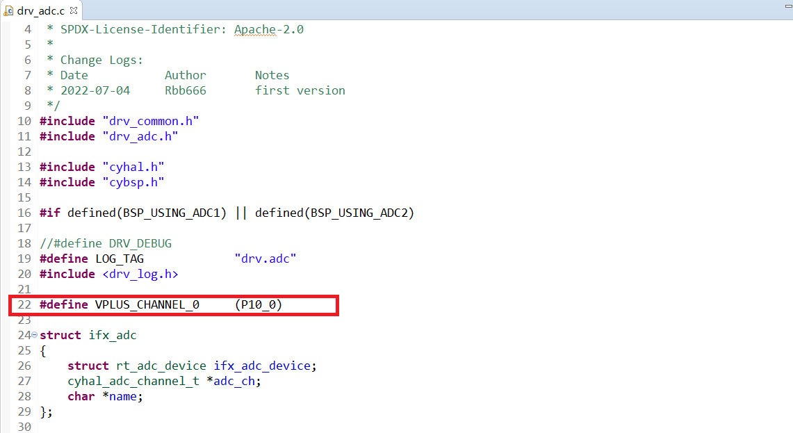
打开libraries/HAL_Drivers/drv_adc.c文件,发现ADC1对应的GPIO为P10.0
OLED配置
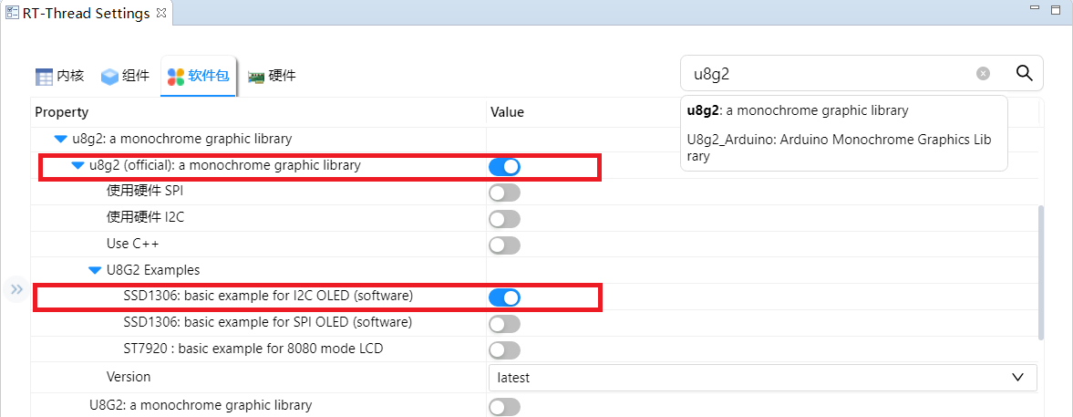
OLED模块的主控是ssd1306,需要在RT-Thread Settings里边使能u8g2软件包,这里使用软件的方式模拟i2c时序
注意要在代码里边绑定i2c引脚,pin number和GPIO的对应关系:P8.0 : 8 x 8 = 64,P8.1 : 8 x 8 + 1 = 65
#define OLED_I2C_PIN_SCL                    64  // P8.0
#define OLED_I2C_PIN_SDA                    65  // P8.1
模块电路
OLED
MCU_ARD_SCL对应P8.0
MCU_ARD_SDA 对应P8.1
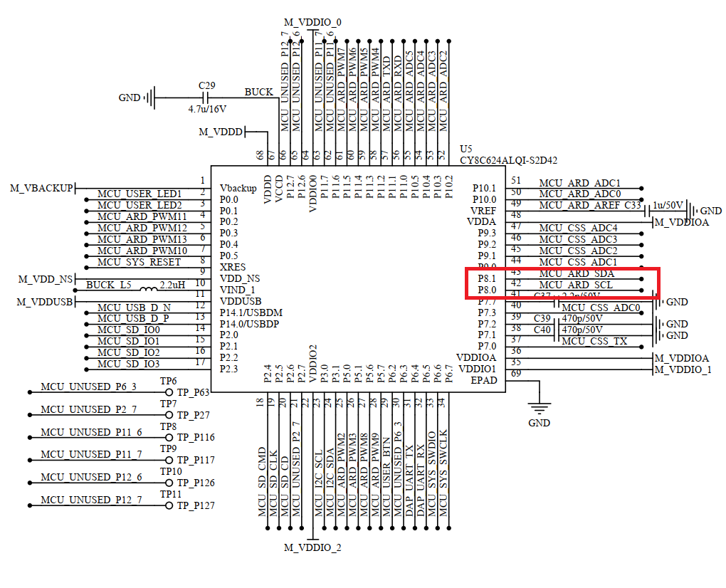
右侧排母从上往下第1、2引脚分别对应SCL、SDA
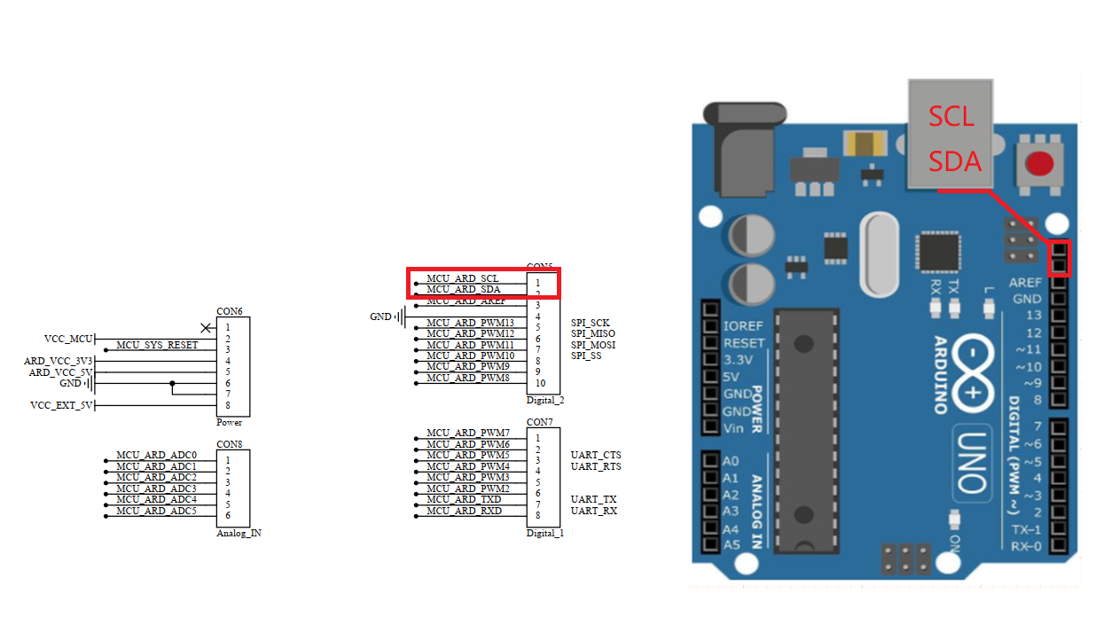
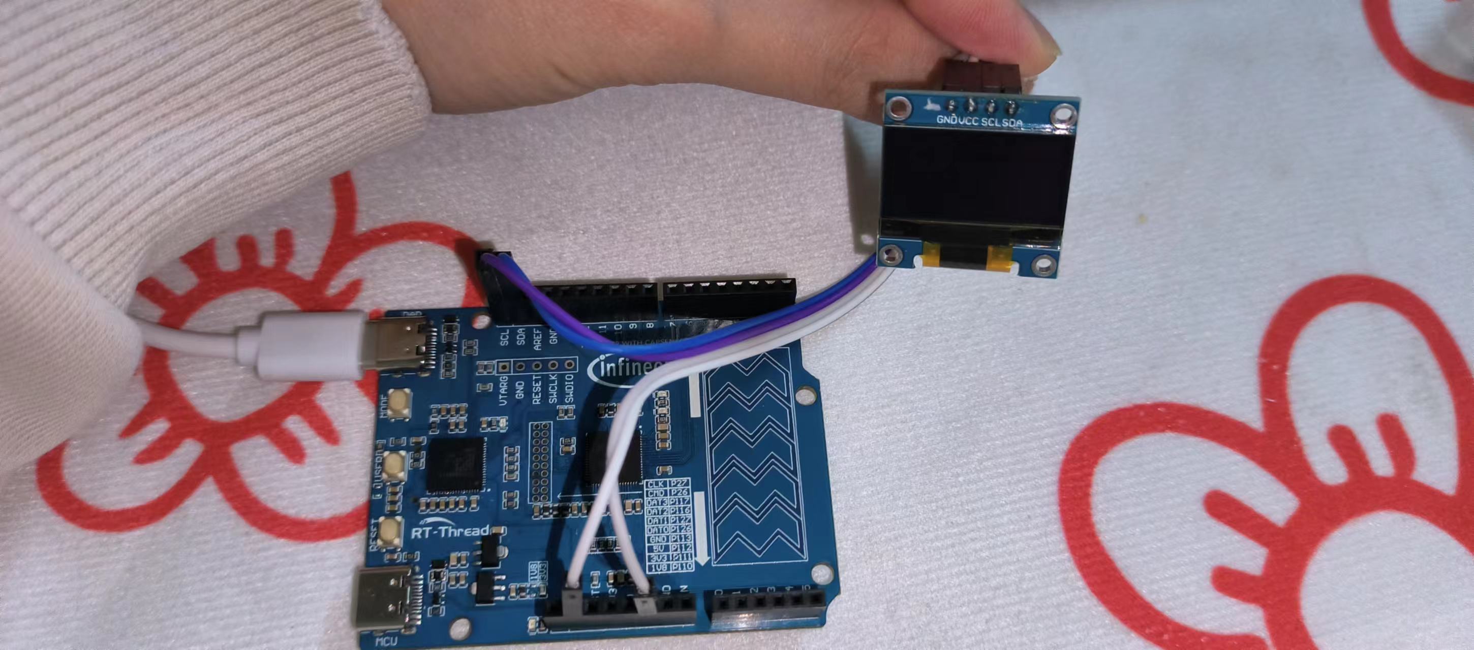
依次连接OLED模块的VCC、GND、SDL、SDA引脚
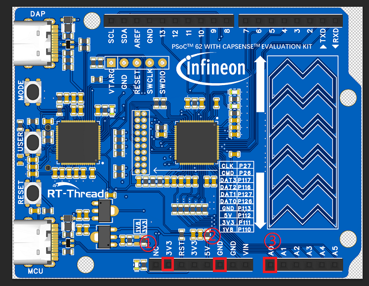
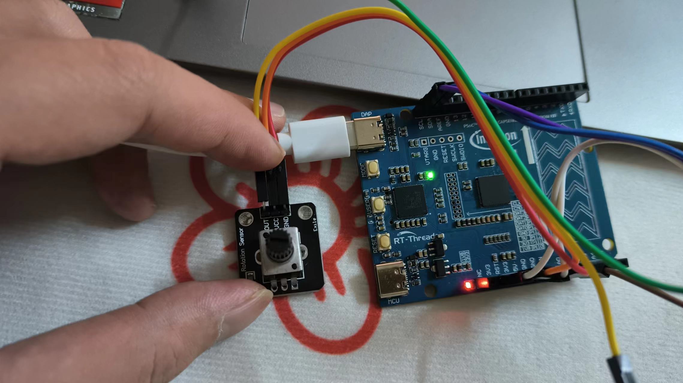
电位器
下图中的①、②、③引脚分别连接电位器的VCC、GND、OUT引脚,③即A0代表P10.0
程序设计
由于RT-Thread给PSoc62™适配的ADC驱动有一些问题,这里需要修改一下电压获取接口,打开libraries/HAL_Drivers/drv_adc.c文件,修改函数ifx_get_adc_value的实现:用cyhal_adc_read_uv接口替代cyhal_adc_read
#define MICRO_TO_MILLI_CONV_RATIO        (1000u)
static rt_err_t ifx_get_adc_value(struct rt_adc_device *device, rt_uint32_t channel, rt_uint32_t *value)
{
    cyhal_adc_channel_t *adc_ch;

    RT_ASSERT(device != RT_NULL);
    adc_ch = device->parent.user_data;

    channel = adc_ch->channel_idx;

#if 1
    *value = cyhal_adc_read_uv(adc_ch) / MICRO_TO_MILLI_CONV_RATIO;
#else
    *value = cyhal_adc_read(adc_ch);
#endif
    return RT_EOK;
}
OLED初始化
// OLED
u8g2_t u8g2;
char buffer[50];
u8g2_Setup_ssd1306_i2c_128x64_noname_f( &u8g2, U8G2_R0, u8x8_byte_sw_i2c, u8x8_gpio_and_delay_rtthread);
u8x8_SetPin(u8g2_GetU8x8(&u8g2), U8X8_PIN_I2C_CLOCK, OLED_I2C_PIN_SCL);
u8x8_SetPin(u8g2_GetU8x8(&u8g2), U8X8_PIN_I2C_DATA, OLED_I2C_PIN_SDA);
u8g2_InitDisplay(&u8g2);
u8g2_SetPowerSave(&u8g2, 0);
ADC1初始化
// ADC1
rt_adc_device_t adc_dev;
rt_uint32_t value;
rt_err_t ret = RT_EOK;

adc_dev = (rt_adc_device_t)rt_device_find(ADC_DEV_NAME);
if (adc_dev == RT_NULL)
{
    rt_kprintf("adc sample run failed! can't find %s device!\n", ADC_DEV_NAME);
}

ret = rt_adc_enable(adc_dev, ADC_DEV_CHANNEL);
if(ret == RT_EOK)
{
    rt_kprintf("adc sample run success!  find %s device!\n", ADC_DEV_NAME);
}
整合代码
#include <rtthread.h>
#include <rtdbg.h>
#include <board.h>
#include <rtdevice.h>
#include <u8g2_port.h>

#define OLED_I2C_PIN_SCL                    64  // P8.0
#define OLED_I2C_PIN_SDA                    65  // P8.1

#define ADC_DEV_NAME        "adc1"
#define ADC_DEV_CHANNEL     0

int main(void)
{
    // OLED
    u8g2_t u8g2;
    char buffer[50];
    u8g2_Setup_ssd1306_i2c_128x64_noname_f( &u8g2, U8G2_R0, u8x8_byte_sw_i2c, u8x8_gpio_and_delay_rtthread);
    u8x8_SetPin(u8g2_GetU8x8(&u8g2), U8X8_PIN_I2C_CLOCK, OLED_I2C_PIN_SCL);
    u8x8_SetPin(u8g2_GetU8x8(&u8g2), U8X8_PIN_I2C_DATA, OLED_I2C_PIN_SDA);
    u8g2_InitDisplay(&u8g2);
    u8g2_SetPowerSave(&u8g2, 0);

    // ADC1
    rt_adc_device_t adc_dev;
    rt_uint32_t value;
    rt_err_t ret = RT_EOK;

    adc_dev = (rt_adc_device_t)rt_device_find(ADC_DEV_NAME);
    if (adc_dev == RT_NULL)
    {
        rt_kprintf("adc sample run failed! can't find %s device!\n", ADC_DEV_NAME);
    }
    /* 使能设备 */
    ret = rt_adc_enable(adc_dev, ADC_DEV_CHANNEL);
    if(ret == RT_EOK)
    {
        rt_kprintf("adc sample run success!  find %s device!\n", ADC_DEV_NAME);
    }

    while(1)
    {
        // read adc value
        value = rt_adc_read(adc_dev, ADC_DEV_CHANNEL);
        memset(buffer, 0, 50);

        if(4294965 <= value) value = 0;
        snprintf(buffer, 50, "Voltage : %d.%02dV\n", value / 1000, value % 1000);

        // display on OLED
        u8g2_ClearBuffer(&u8g2);
        u8g2_SetFont(&u8g2, u8g2_font_ncenB08_tr);

        u8g2_DrawStr(&u8g2, 20, 36, buffer);
        u8g2_SendBuffer(&u8g2);
        cyhal_system_delay_ms(200);
    }
    return 0;
}
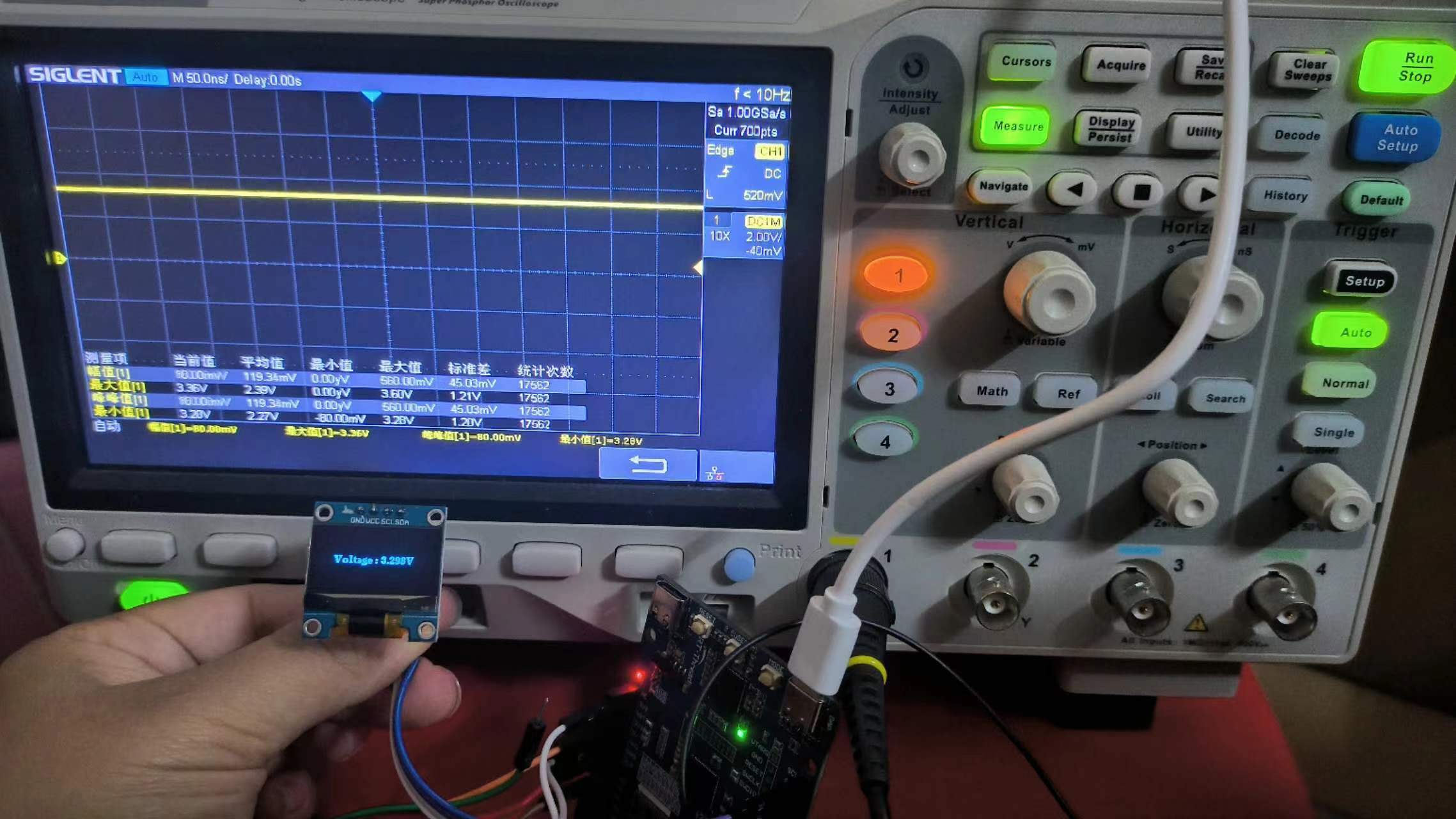
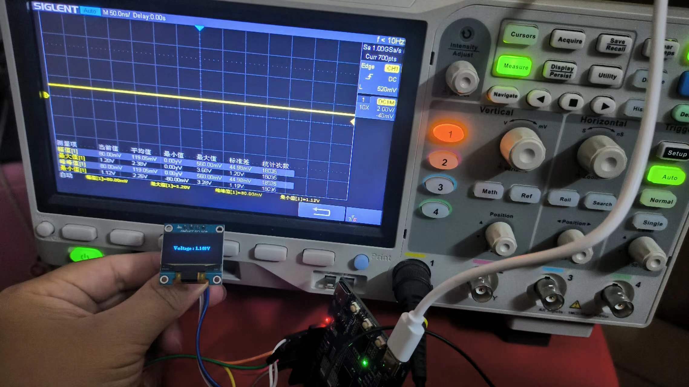
实验效果
使用示波器查看电位器不同旋转位置时的输出电压值,和OLED显示的ADC1电压值做比较,3.3V和1.1V的数值基本吻合
3.3V测量结果
1.1V测量结果
阅读剩余
版权声明:
作者:hywing
链接:https://iotstuff.cn/psoc62-mcu-adc/
文章版权归作者所有,未经允许请勿转载。
THE END